


Inspection is now the tightest constraint on many high-volume lines. A plant running several tonnes per hour cannot station enough people to examine every part, and human judgement drifts across a shift. Buyers have tightened specifications on foreign material, colour consistency and dimensional accuracy, while secondary-material markets pay a premium for purity. Optical sorting has moved from a quality upgrade to a standard unit operation.
An optical sorting machine works by spreading product into a single layer, carrying it through an inspection zone where controlled lighting and cameras or spectral sensors capture an image of every item, comparing each image against accept and reject criteria in real time, and firing a pneumatic or mechanical ejector at the moment a rejected item reaches the separation point. The full cycle, from reflected light to air pulse, usually completes in tens of milliseconds.
What separates a sorter that performs from one that merely runs is the balance between three subsystems.

What an Optical Sorting Machine Really Does
An optical sorting machine is an automated inspection and separation system that evaluates every item in a moving stream against programmed criteria and removes the ones that fail, without touching the ones that pass.
Screens, magnets and density tables sort by a bulk property and can only divide a stream into coarse fractions. An optical sorting machine instead judges each object individually: wrong shade, wrong shape, contaminated, chipped, or the wrong polymer. Inspection is non-destructive, so it runs at full line volume while examining all of production rather than a sample.
The Four Subsystems and Why They Cannot Be Separated
Every platform, from a compact chute sorter to a wide belt machine, contains the same four blocks.
| Subsystem | Function | Typical failure symptom |
| Feed | Spreads material into a monolayer at constant velocity | Overlap hides defects; uneven spacing breaks timing |
| Optical | Illuminates the stream and images every item | Low contrast, motion blur, dirty windows |
| Processing | Classifies against thresholds or a trained model | Unstable thresholds between batches |
| Separation | Deflects rejects out of the main flow | Late or weak pulse, carryover, misses |
The blocks are interdependent, which punishes partial upgrades. A high-resolution camera behind a poorly chosen light source produces a sharp image of a defect it cannot distinguish from the background, and a correct classification delivered three milliseconds late reaches the ejector after the target has passed.
How Optical Sorting Works, Stage by Stage
Optical sorting runs as a continuous four-stage loop, namely singulate the product, illuminate and image it, classify it, and deflect the rejects, with each stage timed against transport speed so that the decision and the physical action land on the same object.
The architecture is documented in reference material on optical sorting, and the sequence below follows it with attention to where accuracy is actually lost.
Stage 1: Feeding and Singulation
Product passes a hopper and is spread by a vibratory feeder, levelling belt or accelerating conveyor until items travel in a single layer at consistent spacing. Two overlapping parts present one silhouette, so a defect on the hidden face is invisible. Uneven spacing is equally damaging, because the ejector is a fixed nozzle array and an item arriving late receives a pulse aimed where it should have been.
Stage 2: Detection in the Inspection Zone
Light sources illuminate each item and cameras capture reflected, transmitted or emitted light. Reflectance carries colour, texture and shape. Transmission, produced by backlighting, carries silhouette and internal structure. Emission, usually fluorescence under ultraviolet excitation, carries material identity for specific contaminants.
Stage 3: Classification and the Decision Window
The processor extracts hue, area, contour, aspect ratio, texture and spectral response from each object, then compares that vector against operator thresholds or a trained model. The range of features a sorter can evaluate is broad, as an overview of visual inspection functions makes clear, though only a subset matters for any given product. The binding constraint is temporal rather than computational. The decision must arrive before the object leaves the ejection window, which at 3 metres per second and a 300 millimetre separation means roughly 100 milliseconds of total budget.
Stage 4: Ejection and Verification
Rejects are deflected into a separate chute while accepted product continues on its trajectory. Two numbers describe the outcome and pull against each other. Removal efficiency is the share of true defects ejected. Carryover, or good product loss, is the share of acceptable product removed by mistake. Tightening thresholds improves the first and worsens the second, so a sorter is well tuned only when both sit inside the commercial tolerance for that product.

The Camera System: What the Machine Can See
The camera sets what the machine is able to detect, and its two governing specifications are spatial resolution, which fixes the smallest visible defect, and scan rate, which fixes the line speed before motion blur destroys that resolution.
Monochromatic, Colour and Trichromatic Cameras
A monochromatic camera records brightness only. It is cheap and fast, and effective where defects differ strongly in luminance, such as dark stones in white rice or bright chips on dark plastic. A colour camera splits light into red, green and blue channels and grades by hue, which matters for burnt kernels and mixed-colour regrind. Trichromatic designs extend the principle into bands chosen for a specific application, sometimes including near-infrared or ultraviolet, so the channel set maximises separation rather than reproducing human vision.
Resolution, Line Rate and the Smallest Detectable Defect
Resolution is best expressed as millimetres per pixel rather than megapixels, because field of view matters as much as sensor size. A defect needs two to three pixels across to be segmented consistently.
| Sensor width | Field of view | Pixel size | Smallest reliable defect |
| 2048 px | 400 mm | 0.20 mm | 0.4 to 0.6 mm |
| 4096 px | 600 mm | 0.15 mm | 0.3 to 0.45 mm |
| 8192 px | 800 mm | 0.10 mm | 0.2 to 0.3 mm |
A faster line needs a shorter exposure to avoid blur, and a shorter exposure needs more light, so lighting and camera choice become one problem. Mounting several cameras on the same line, as in six-sided appearance inspection, is the usual answer for small parts whose critical features sit on different faces.
How a Colour Sorter Differs from a Spectral Sorter
A colour sorter images visible reflectance and separates on hue, saturation and shape. It performs well when the defect looks different and fails when it does not, as with black plastic in black plastic. Spectral sensing closes that gap by interrogating composition. Near-infrared instruments measure absorption at molecular vibration bands, so polymers return distinct signatures regardless of colour, a basis described in references on near-infrared spectroscopy.
| Sensor | Signal measured | Limitation |
| RGB camera | Visible reflectance | Cannot see composition |
| NIR, 900 to 1700 nm | Molecular absorption | Needs calibration, weak on dark surfaces |
| Laser | Reflectance at one wavelength | Single spectral point |
| X-ray transmission | Density attenuation | Cost, radiation handling |
| Hyperspectral | Hundreds of narrow bands | Data volume, slower throughput |

Lighting: The Subsystem That Decides Contrast
Lighting determines whether a defect produces a usable signal at all, and it is usually the cheapest performance lever, since a change of geometry or wavelength can outperform a camera upgrade.
Imaging measures light, so the geometry that delivers light to the part controls what the sensor can distinguish. The configurations used across machine vision translate directly into sorting.
| Geometry | Light delivery | What it reveals |
| Bright field | Direct, near the camera axis | Surface colour, print, general appearance |
| Dark field | Shallow grazing angle | Scratches, cracks, burrs, raised contamination |
| Backlight | Diffuse panel behind the part | Silhouette, holes, missing features |
| Diffuse dome | Soft, omnidirectional | Shiny or curved parts prone to glare |
| Coaxial | Through the lens axis | Flat reflective surfaces such as polished metal |
Many defects are geometric rather than chromatic. A hairline crack on a machined fastener may be invisible under frontal illumination yet appear as a bright line under grazing light, because the crack scatters light toward the lens while the surrounding surface reflects it away.
Contrast also depends on wavelength. Blue light on a yellow flaw suppresses the background and darkens the flaw, while a bandpass filter that rejects ambient light can lift a marginal contrast ratio into a robust one. Ultraviolet excitation adds a third option, since some adhesives, oils and biological contaminants fluoresce under UV while the substrate does not.
LED arrays have displaced halogen sources because they switch in microseconds, letting a strobe pulse synchronise with the camera shutter and freeze motion. Two problems remain. Heat degrades output over thousands of hours, so intensity must be referenced against a white target at intervals, and dust or condensation on the window attenuates light, producing a slow loss of accuracy that operators notice only when rejection rates drift.
Ejection: Turning a Decision into Physical Separation
The ejection system converts a classification into a physical outcome, and its performance is bounded by valve response time, pulse duration and the accuracy of the delay calculated between detection and arrival at the nozzle.
Detection accuracy is worthless without timing accuracy. When the camera identifies a defect, the object keeps travelling toward the ejector array, so the controller must compute the transit delay from measured velocity and distance and then open the correct valve for the correct interval.
| Parameter | Typical range | Effect of getting it wrong |
| Valve response time | 0.5 to 1 ms | Late pulse misses the target |
| Pulse duration | 5 to 20 ms | Too short, incomplete deflection; too long, extra carryover |
| Detection to ejection distance | 200 to 400 mm | Sets timing budget and speed sensitivity |
| Air pressure | 3 to 7 bar | Low pressure under-deflects; excess disturbs neighbours |
At 3 metres per second an object moves 3 millimetres every millisecond, so a valve opening one millisecond late strikes the trailing edge of the target or clips its neighbour. Nozzle bore and angle then decide how much of the pulse lands where it should. Small bores conserve air but lose force over distance, while large bores deflect reliably but disturb nearby product.
Air quality is the most neglected variable in the machine. Moisture, oil carryover and particulates clog orifices, cause valves to under-fire and contaminate product, so a dryer, coalescing filter and dew point checks are not optional on a three-shift line.
Pneumatic ejection dominates because it is fast and non-contact, but heavy items need air volumes that make consumption expensive, and fragile items can be damaged by the pulse. Flap gates, swing arms and retracting belts are used where objects are large, high value, or need to be placed rather than deflected, at the cost of cycle time.

Types of Optical Sorting Machines
Sorters are classified along two independent axes, the transport platform that presents material to the optics and the sensor set that performs the inspection, and the right combination is dictated by product geometry rather than budget.
| Platform | Product presentation | Best suited to |
| Belt | Monolayer on a flat or inclined belt | Irregular or fragile items needing stable orientation |
| Chute | Free fall through a vertical channel | Free-flowing granular material at high capacity |
| Glass turntable | Spread on a rotating transparent disc | Small parts inspected from above and below |
| Index plate | Located in pockets at fixed pitch | Precision parts needing repeatable position |
| Steel belt | Metal carrier with high wear resistance | Abrasive, hot or heavy material |
Single-sensor machines are simpler to calibrate and faster to decide. Multi-sensor machines fuse colour with near-infrared and laser data, which sharpens discrimination but adds complexity, because channels must be spatially registered and their thresholds interact.
Where Optical Sorting Machines Are Used
Optical sorting is applied wherever a stream contains items that must be separated by appearance or composition, from bulk agricultural commodities to micrometre-scale electronic components.
In food and agriculture, sorters remove discoloured kernels, stones and plastic, and grade by colour and size. In recycling they separate polymers by resin type and glass by colour. In mining they pre-concentrate ore before grinding, saving energy downstream.
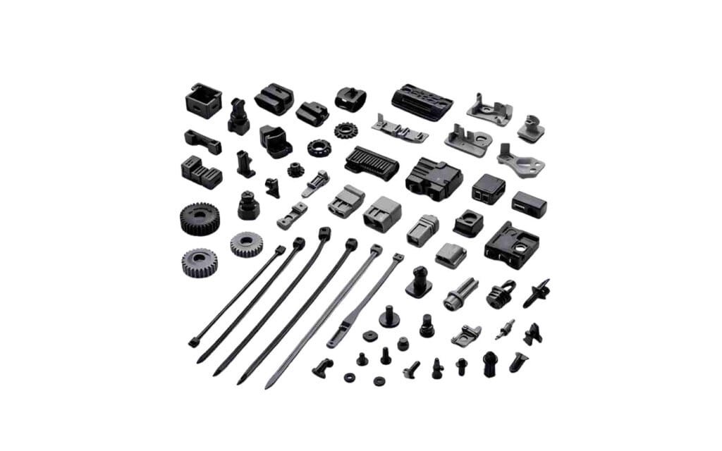
Precision manufacturing is the fastest-growing segment and imposes requirements bulk sorters rarely face. Fasteners are checked for thread damage and plating faults, rubber seals for flash and dimensional drift, and electronic components across multiple faces at high count rates, which is why electronics industry sorting relies on turntable and index-plate platforms with multi-view optics.
FAQ
Can an optical sorting machine separate materials that look identical? Yes, provided a sensor sees a property other than colour. Near-infrared channels distinguish polymers by molecular absorption, laser sensors detect transparent contaminants that share the product colour, and X-ray transmission separates by density. The limit is contrast rather than principle: if two materials return indistinguishable signals in every band, no software will separate them reliably.
Can one machine apply several sorting criteria at once? Most sorters evaluate multiple features in a single pass and combine colour, shape, texture and spectral rules into one decision. Throughput cannot be combined freely, however. Each added criterion narrows the accept window, which usually raises carryover, and sensor fusion adds calibration overhead.
How much do temperature, humidity and vibration affect stability? More than most specifications admit. LED output falls as junction temperature rises, so an uncorrected warm-up period shifts apparent colour. Condensation on cooled windows scatters light where cold product meets humid air. Vibration and speed fluctuation blur images and shift ejection timing. Enclosure cooling, air purging and encoder-synchronised triggering address all three.